Power Connection Upgrade to NEQ6 Pro
Over the last year I have noticed that my NEQ6 would sometimes loose power. Over the course of a few months I tracked this down to the 2.5mm DC socket having worn, probably due to the cable being pulled as the mount slewed over the last 3 years use.
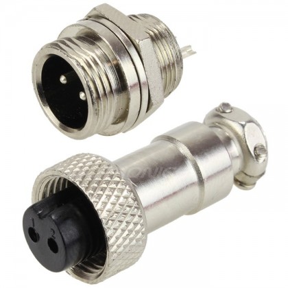
It would have been possible to replace the existing socket with an identical one but I decided to move to something more robust, interestingly the new EQ6-R has done just this. I chose to move to a heavy duty locking plug and socket, something that traditionally was used for CB radio equipment. I went for the 12mm diameter version as there is not a huge amount of space to fit it since the PCB is close to the front plate. If you Google GX12 you will see examples like the photo below, you will only need 2-pins but I struggled to get one so I ordered the 3-pin variant from Amazon. The GX12 is less common than the GX16, the difference being the GX16 is larger.
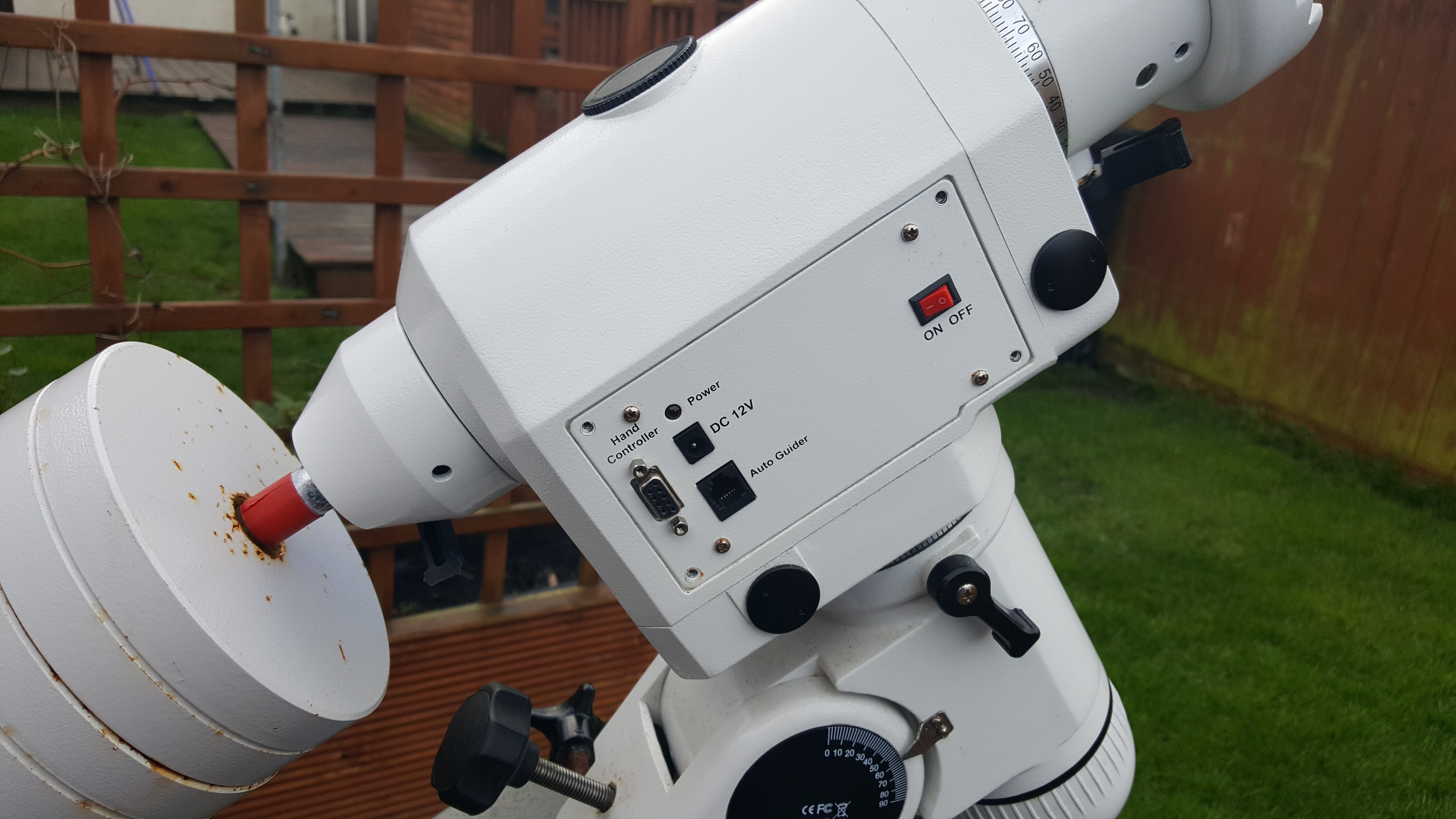
The first step is to remove the mounts connector plate, the photo below shows the 4 retaining screws removed.
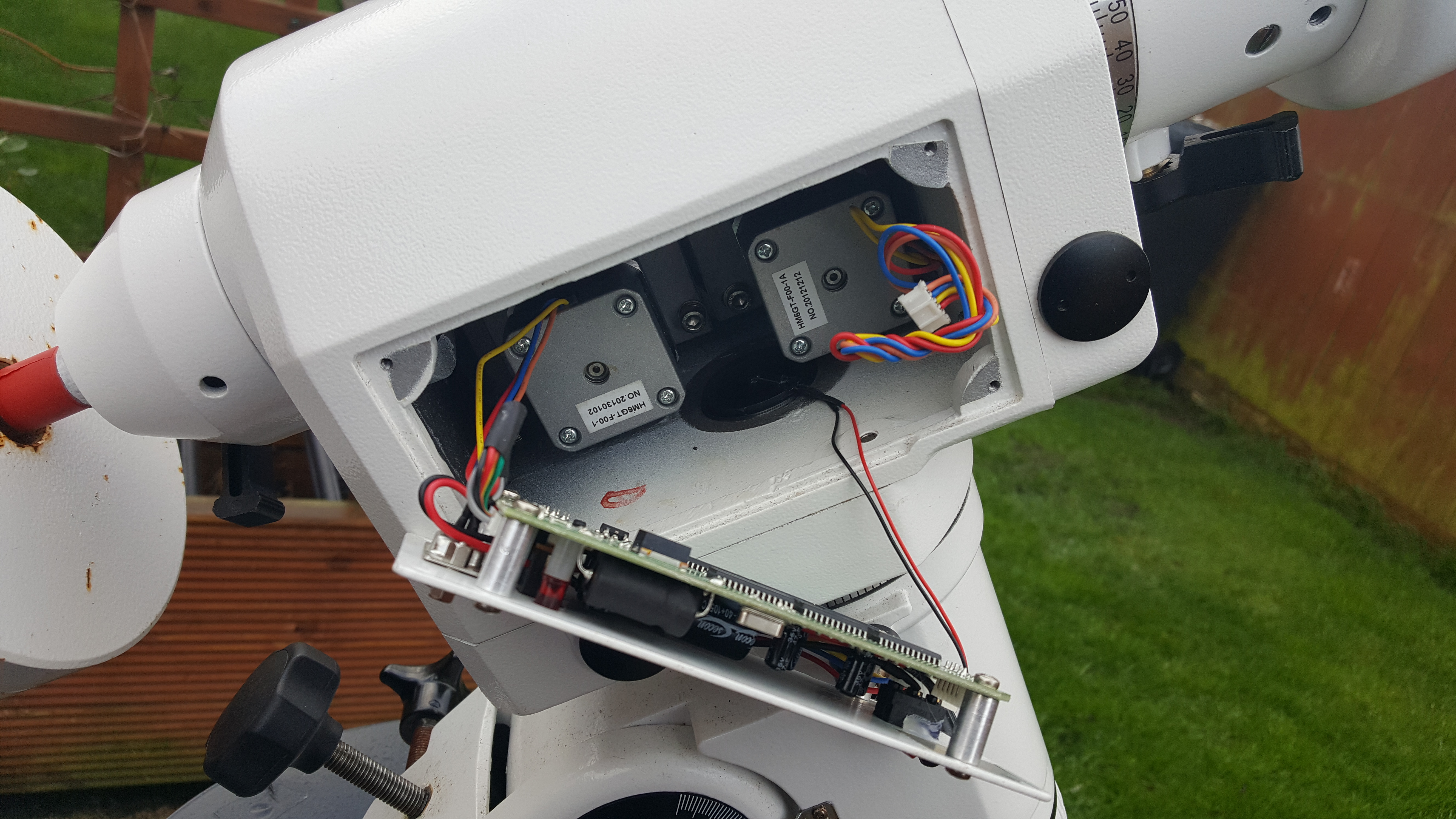
This allows the plate to be pulled forward, exposing the PCB and wiring. [Note: in the photo below I have already removed one of the motor connections]
Remove the two motor cable connections (make sure to note which one goes where) along with the polar scope LED cable. This allows you to completely remove the plate and PCB from the mount. In the photo below I have shown, with dimensions in mm, the position where I chose to fit my new socket.
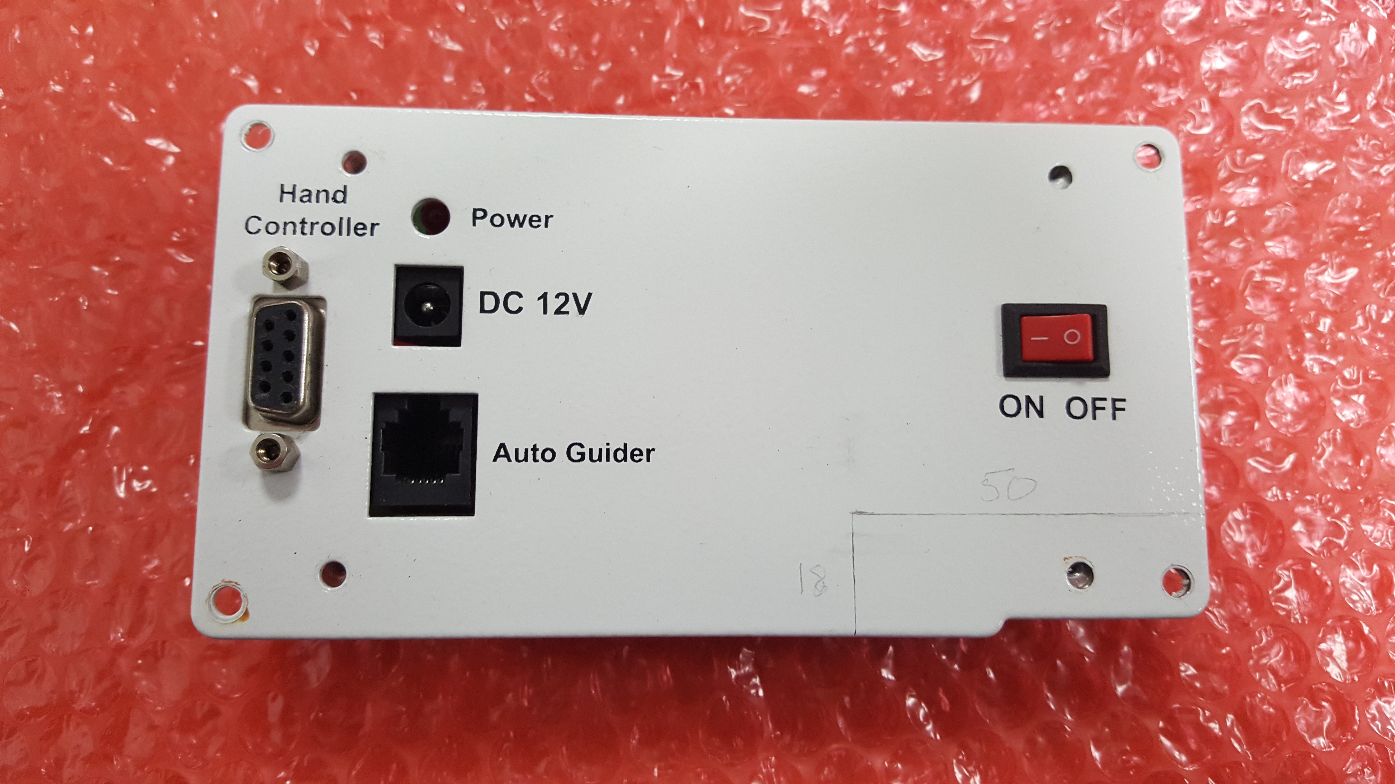
Once you have done this you should remove the PCB from the plate by unscrewing the 4 remaining screws on the plate. Then disconnect the wires from the power switch and DB-9 connector used to connect to your PC or handset.
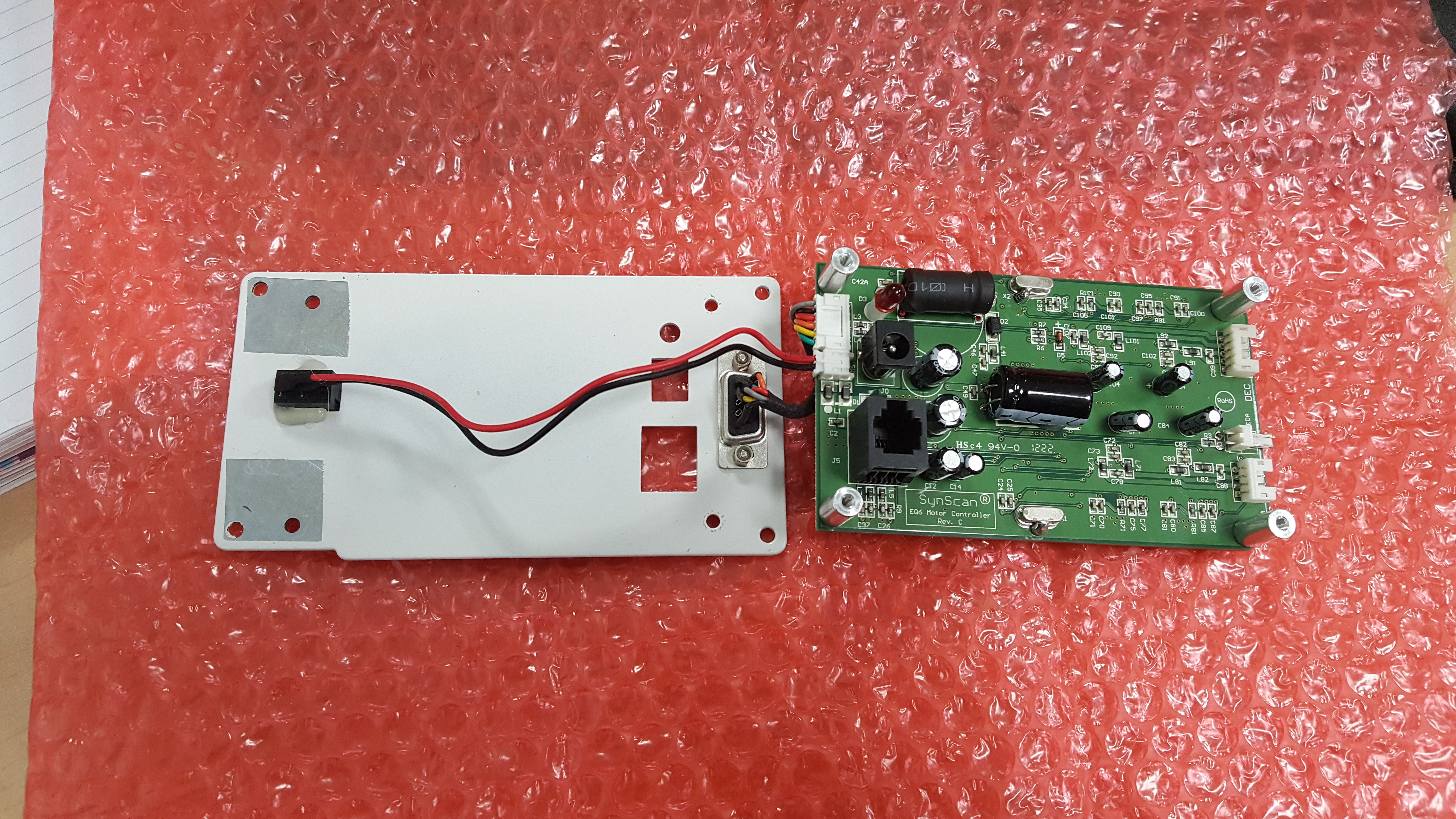
Now drill the hole in the chosen location, my hole needed to be 12mm for the GX12. The GX16 will be 16mm. [Note: you can ignore my insulating tape and bubble wrap as I did this to avoid removing the PCB, which I ended up doing anyway]
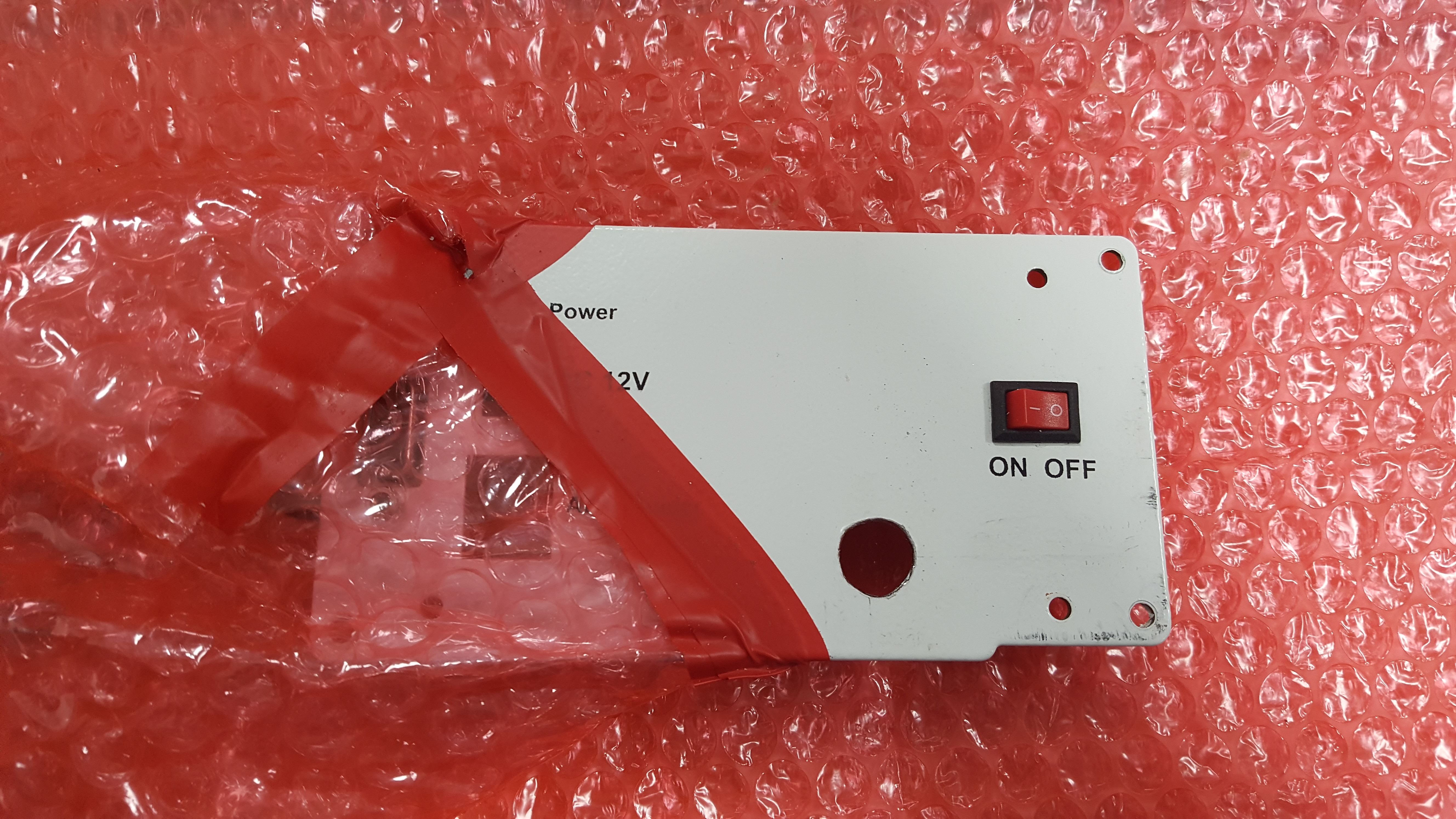
With the hole drilled you can fit the new socket. I kept the sprung washer to the outside to give a little extra clearance between the PCB and rear of the socket.
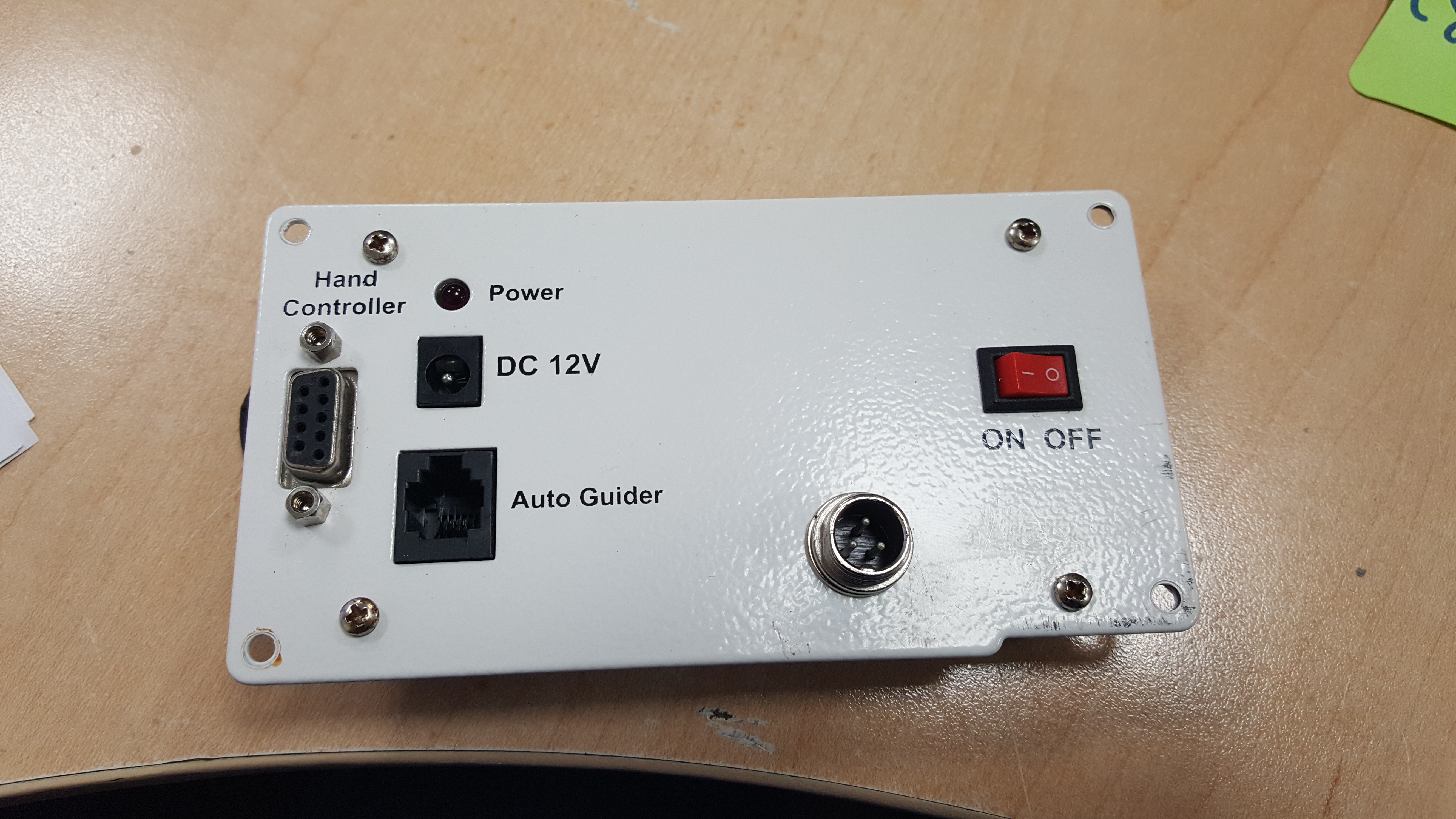
Now solder some power cable onto the socket and refit the PCB.
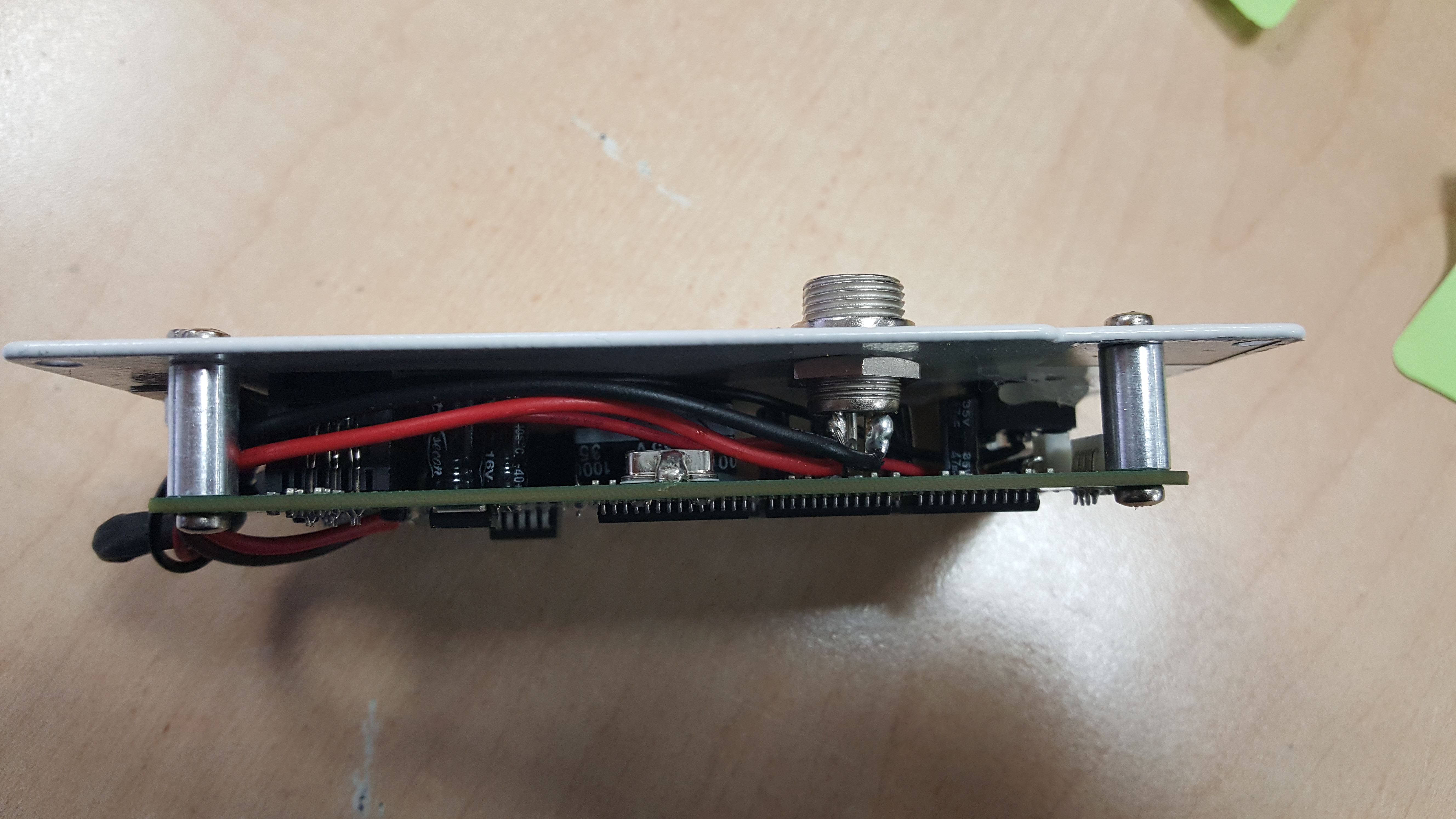
I chose to route the power cabling around one of the corner bosses as this would allow more flexibility if I needed to remove the PCB in the future. If you run it the shortest route you could find yourself having a very short cable. Solder the other end of the wires to the pads shown below. You can test the connection using a standard multimeter by doing a continuity test between the old socket centre pin (positive) and the pin you have chosen to be positive on the new socket.
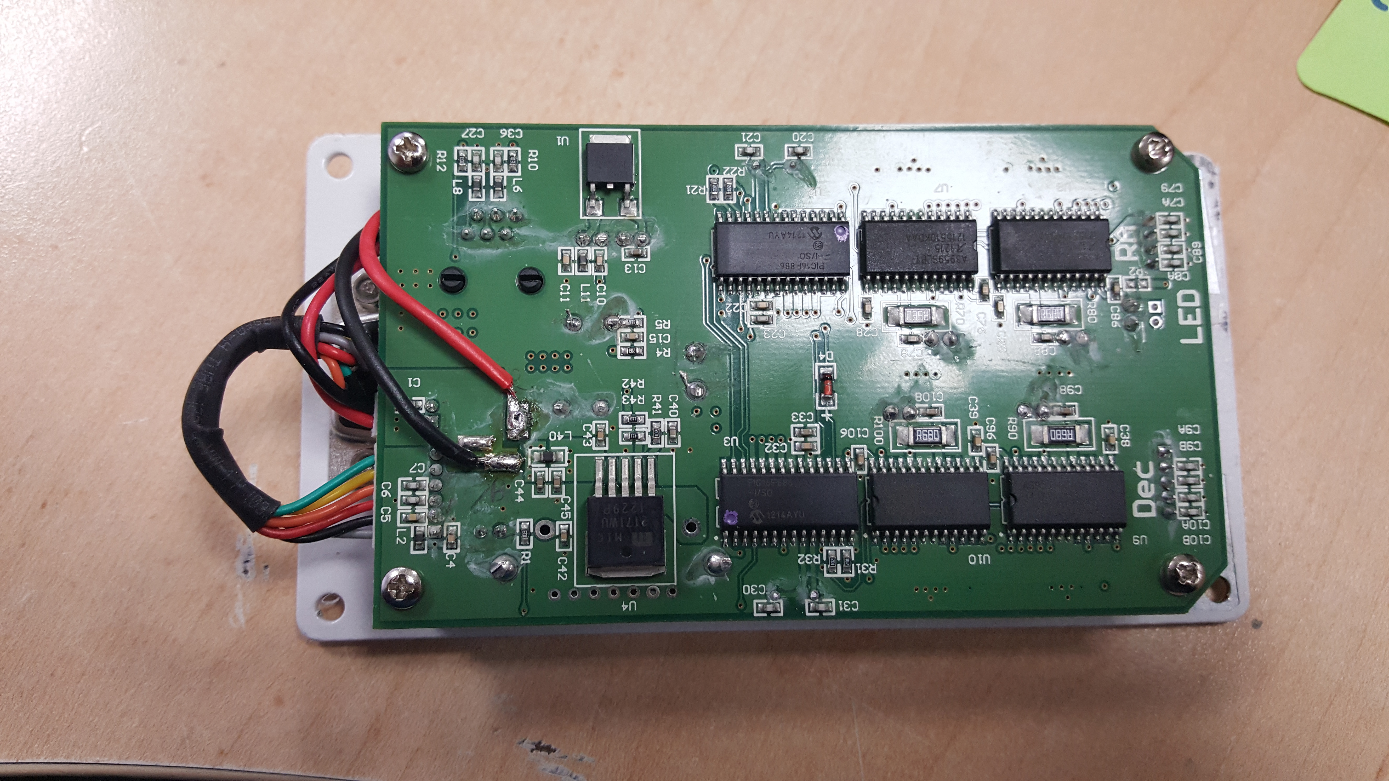
Now simply refit the plate and PCB to your mount, making sure to connect the RA & Dec motor to the right connector.
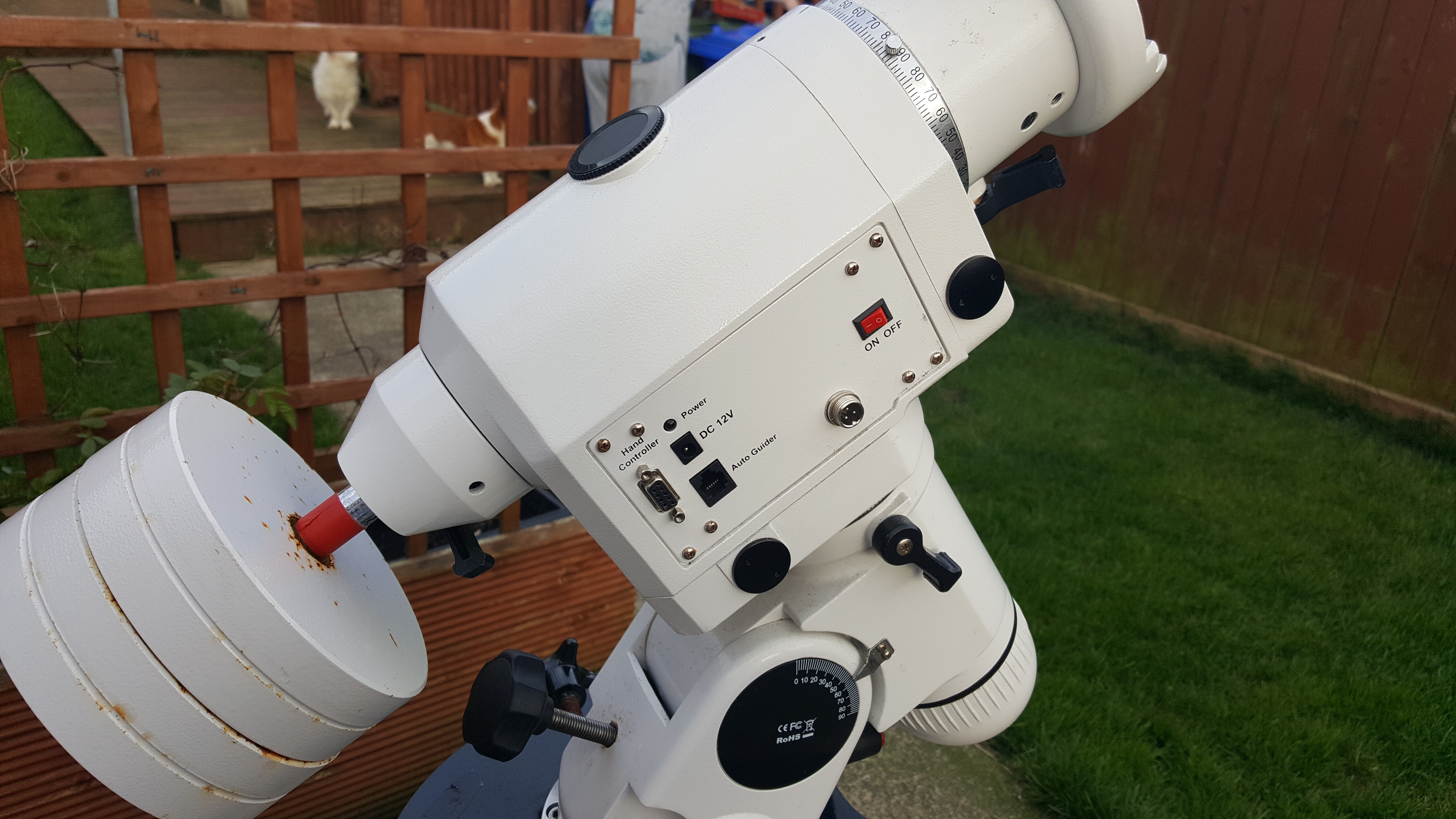
And that's it... you now have a much more robust power connection on your mount, as well as the option to use the original connector if needed. I see no reason why you couldn't plug a power supply into both at the same time but something tells me you probably shouldn't.
The next step is to make a new power cable to suit, you can either do this by cutting the lead off your existing supply or by making a new cable. I chose the latter and tested with a new control system I am getting ready to install at the pier this summer.
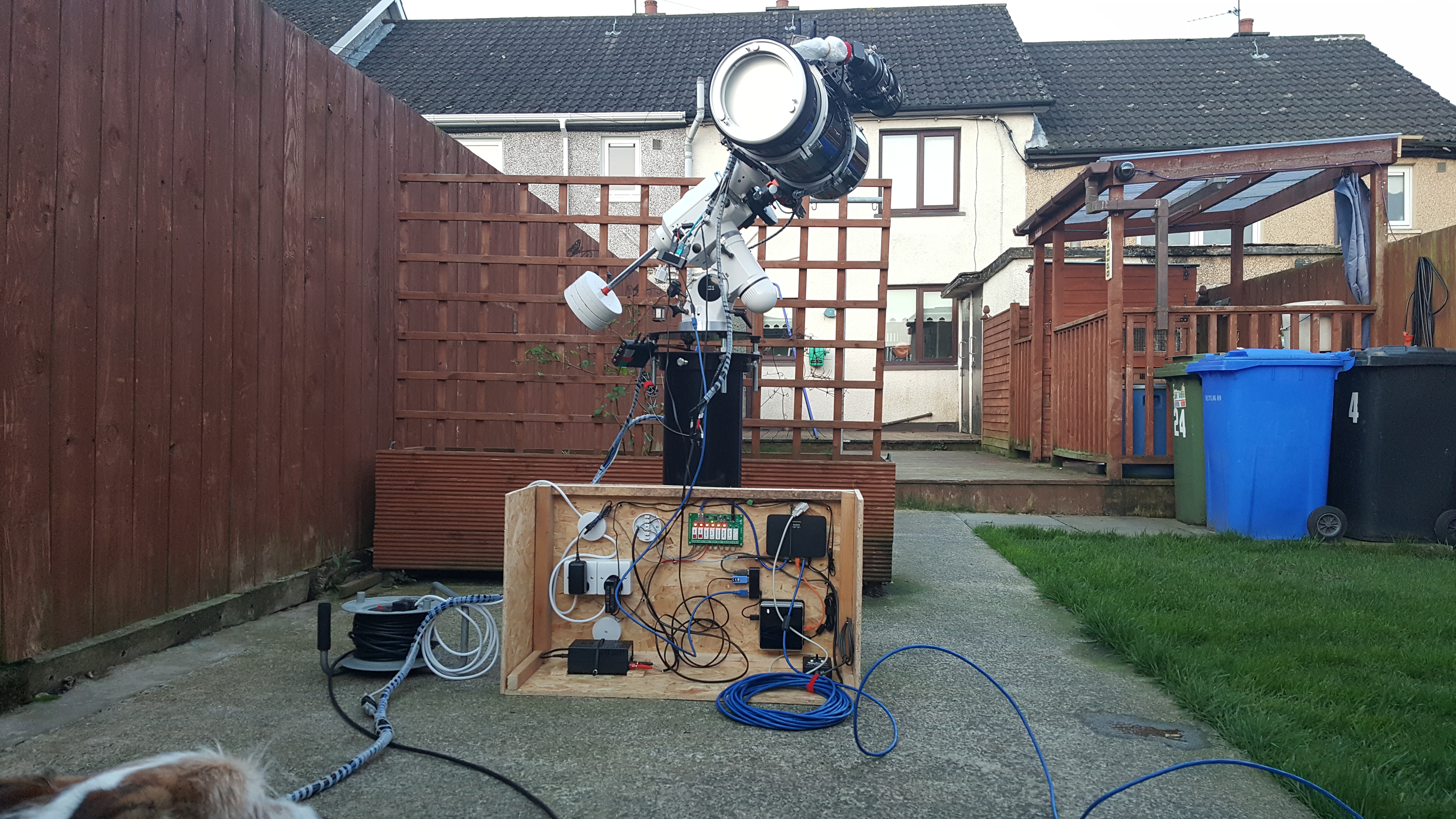
I hope you find this guide useful, if you have any questions just drop me an email using the contact tab of my website.
